
基板図

部品面

ハンダ面

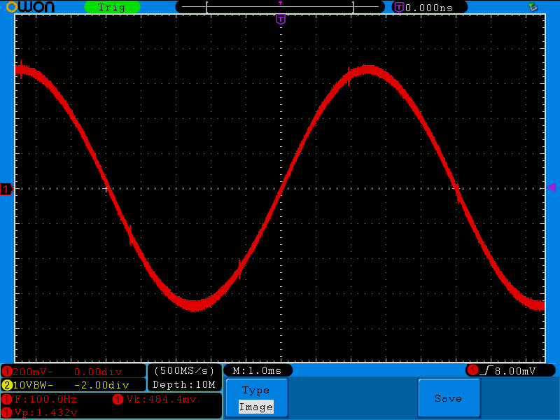
消費電流 3mA
10kΩ負荷、100Hz出力時。
Github:
https://github.com/ryood/SPI_Wein_Bridge_Osc
メモ:
増幅率を決める5kΩのトリムPOTは調整がちょっとむずかしいので、多回転タイプの方が良かったかも。


| Vr | 発振周波数(Hz) | 振幅(Vp-p) |
|---|---|---|
| 0 | 6677 | 1.14 |
| 1 | 3828 | 1.69 |
| 2 | 2703 | 1.88 |
| 3 | 2089 | 2.05 |
| 4 | 1698 | 2.16 |
| 5 | 1433 | 2.26 |
| 6 | 1238 | 2.38 |
| 7 | 1089 | 2.5 |
| 8 | 972.8 | 2.62 |
| 9 | 878.7 | 2.74 |
| 10 | 801.3 | 2.84 |
| 11 | 736.4 | 2.86 |
| 12 | 681.2 | 2.98 |
| 13 | 632.9 | 3.02 |
| 14 | 592.4 | 3.06 |
| 15 | 555.6 | 3.08 |
| 23 | 375.2 | 3.12 |
| 31 | 282.1 | 3.34 |
| 39 | 226.2 | 3.38 |
| 47 | 188.7 | 3.48 |
| 55 | 162.1 | 3.42 |
| 63 | 141.8 | 3.48 |
| 71 | 125.9 | 3.6 |
| 79 | 113.6 | 3.64 |
| 95 | 94.6 | 3.6 |
| 104 | 86.6 | 3.72 |
| 111 | 81.1 | 3.76 |
| 127 | 71 | 3.78 |
| 143 | 63 | 3.74 |
| 159 | 56.8 | 3.76 |
| 191 | 47.3 | 3.84 |
| 223 | 40.6 | 3.84 |
| 255 | 35.5 | 3.8 |


/*
  Wein Bridge Control

  AD8402

  POTの出力電圧を読み取って
  Digi-Potのチャンネル1, 2の抵抗値を可変

  Pinの接続
  A0 POT1
  10 CS
  11 MOSI
  13 SCK
*/

// inslude the SPI library:
#include <SPI.h>

// set pin 10 as the slave select for the digital pot:
const int slaveSelectPin = 10;

byte v0;

void setup() {
  // set the slaveSelectPin as an output:
  pinMode (slaveSelectPin, OUTPUT);
  digitalWrite(slaveSelectPin, HIGH);
  // initialize SPI:
  SPI.begin();
  delay(1);

  Serial.begin(9600);
  Serial.println("Wein Bridge Test.");
}

void loop() {
  int v = analogRead(0) / 4;
  if (v != v0) {
    v0 = v;

    Serial.print(v0);
    Serial.print("\n");

    digitalPotWrite(0, v0);
    digitalPotWrite(1, v0);
  }
}

void digitalPotWrite(int address, int value) {
  // take the SS pin low to select the chip:
  digitalWrite(slaveSelectPin, LOW);
  //  send in the address and value via SPI:
  SPI.transfer(address);
  SPI.transfer(value);
  // take the SS pin high to de-select the chip:
  digitalWrite(slaveSelectPin, HIGH);
}


| channel | 最小(Ω) | 最大(Ω) |
|---|---|---|
| RDAC1 | 50.9 | 8750 |
| RDAC3 | 51.9 | 8720 |


/*
  Wein Bridge Control

  AD8403

  POTの出力電圧を読み取って
  Digi-Potのチャンネル1, 3の抵抗値を可変

  Pinの接続
  A0 POT1
  10 CS
  11 MOSI
  13 SCK
*/

// inslude the SPI library:
#include <SPI.h>

// set pin 10 as the slave select for the digital pot:
const int slaveSelectPin = 10;

byte cnt;
byte v0, v1;

void setup() {
  // set the slaveSelectPin as an output:
  pinMode (slaveSelectPin, OUTPUT);
  digitalWrite(slaveSelectPin, HIGH);
  // initialize SPI:
  SPI.begin();
  delay(1);

  Serial.begin(9600);
  Serial.println("Wein Bridge Test.");
}

void loop() {
  v0 = analogRead(0) / 4;

  Serial.print(v0);
  Serial.print("\n");

  digitalPotWrite(0, v0);
  digitalPotWrite(2, v0);
  delay(1);
}

void digitalPotWrite(int address, int value) {
  // take the SS pin low to select the chip:
  digitalWrite(slaveSelectPin, LOW);
  //  send in the address and value via SPI:
  SPI.transfer(address);
  SPI.transfer(value);
  // take the SS pin high to de-select the chip:
  digitalWrite(slaveSelectPin, HIGH);
}



// inslude the SPI library:
#include <SPI.h>

// set pin 10 as the slave select for the digital pot:
const int slaveSelectPin = 10;

void setup() {
  // set the slaveSelectPin as an output:
  pinMode(slaveSelectPin, OUTPUT);
  // initialize SPI:
  SPI.begin();
}

void loop() {
  // go through the four channels of the digital pot:
  for (int channel = 0; channel < 4; channel++) {
    // change the resistance on this channel from min to max:
    digitalPotWrite(channel, 255);
    digitalPotWrite(channel, 0);
  }
}

void digitalPotWrite(int address, int value) {
  // take the SS pin low to select the chip:
  digitalWrite(slaveSelectPin, LOW);
  //  send in the address and value via SPI:
  SPI.transfer(address);
  SPI.transfer(value);
  // take the SS pin high to de-select the chip:
  digitalWrite(slaveSelectPin, HIGH);
}


/*
 * Digital Potentiometer AD8304のテスト
 *
 * 2017.06.28
 *
 */

#include "mbed.h"

#define SPI_CLOCK   (16000000)

SPI SpiM(SPI_MOSI, SPI_MISO, SPI_SCK);  // mosi, miso, sclk
DigitalOut Cs(D10, 1);

// address: 0..4
// value:   0..255
void outDigiPot(uint8_t address, uint8_t value)
{
    Cs = 0;
    SpiM.write(address);
    SpiM.write(value);
    Cs = 1;
}

int main()
{
    SpiM.format(8, 0);
    SpiM.frequency(SPI_CLOCK);

    for (;;) {
        for (int channel = 0; channel < 4; channel++) {
            outDigiPot(channel, 255);
            wait_us(1);
            outDigiPot(channel, 0);
            wait_us(1);
        }
    }
}


| Device | SCK(設定値) | SCK(実測値) | CS |
|---|---|---|---|
| Arduino | 4MHz | 4MHz | 9.680us |
| F446RE | 1MHz | 597.0kHz | 26.24us |
| F446RE | 6MHz | 5.627MHz | 7.820us |
| F446RE | 12MHz | 11.25MHz | 6.22us |
| F303K8 | 1MHz | 1MHz | 34.6us |
| F303K8 | 8MHz | 8MHz | 20.8us |
| F303K8 | 16MHz | 16MHz | 20.84us |
