STM32のADCはポーリングの他に、割り込みやDMAを使う事もでき、こちらのほうがCPU時間を節約できそうです。
参考にした記事
STM32CubeのExample「ADC_RegularConversion_Polling」
<STM32Cube>\Repository\STM32Cube_FW_F4_V1.24.0\Projects\STM32446E_EVAL\Examples\ADC\ADC_RegularConversion_Polling
「ガレスタさんのDIY日記」さんの「STM32でADCをやってみる1(レギュラ変換)」
「CCWO」さんの「STM32F303K8 ADC 1ch レギュラー変換」
実行環境
- Nucleo-F446RE
- STM32CubeMX Version 5.1.0
- System Workbench for STM32 - C/C++ Embedded Development Tools for MCU Version: 2.8.1.201903050911
シングル変換
プロジェクト:
https://github.com/ryood/STM32Cube_Test/tree/master/SW4STM32/Nucleo-F446_ADC_Polling_Test1
STM32CubeのExample「ADC_RegularConversion_Polling」をもとに「シングル変換(Continuous Conversion Mode: DISALBE)」で動作させました。「ガレスタさんのDIY日記」さんや「CCWO」さんの例では「連続変換(Continuous Conversion Mode: Enable)」である点が異なります。
STM32CubeMXの設定
ADC1のIN0を有効化します。PinoutビューでPA0がADC入力に割り当てられます。PA0はNucleo-F446REのArduino HeaderのA0につながっています。

Configurationはデフォルトのままです。

SW4STM32でコードを追加(一部抜粋)
/* Private includes ----------------------------------------------------------*/
/* USER CODE BEGIN Includes */
#include <stdio.h>
/* USER CODE END Includes */
<stdio.h>をインクルード。
/* Private user code ---------------------------------------------------------*/
/* USER CODE BEGIN 0 */
#ifdef __GNUC__
#define PUTCHAR_PROTOTYPE int __io_putchar(int ch)
#else
#define PUTCHAR_PROTOTYPE int fputc(int ch, FILE *f)
#endif
PUTCHAR_PROTOTYPE
{
 HAL_UART_Transmit(&huart2, (uint8_t *)&ch, 1, 0xFFFF);
 return ch;
}
/* USER CODE END 0 */
printf()を使えるようにする。
  /* Infinite loop */
  /* USER CODE BEGIN WHILE */
  while (1)
  {
    /* USER CODE END WHILE */

    /* USER CODE BEGIN 3 */
   /*##-3- Start the conversion process #######################################*/
   if (HAL_ADC_Start(&hadc1) != HAL_OK)
   {
  /* Start Conversation Error */
  Error_Handler();
   }

   /*##-4- Wait for the end of conversion #####################################*/
   /*  Before starting a new conversion, you need to check the current state of
     the peripheral; if it痴 busy you need to wait for the end of current
     conversion before starting a new one.
     For simplicity reasons, this example is just waiting till the end of the
     conversion, but application may perform other tasks while conversion
     operation is ongoing. */
   if (HAL_ADC_PollForConversion(&hadc1, 10) != HAL_OK)
   {
  /* End Of Conversion flag not set on time */
  Error_Handler();
   }

 /* Check if the continuous conversion of regular channel is finished */
   if ((HAL_ADC_GetState(&hadc1) & HAL_ADC_STATE_EOC_REG) == HAL_ADC_STATE_EOC_REG)
   {
  /*##-5- Get the converted value of regular channel  ########################*/
  uhADCxConvertedValue = HAL_ADC_GetValue(&hadc1);
   }
   printf("ADC Value: %d\r\n", uhADCxConvertedValue);
   HAL_Delay(100);
  }
  /* USER CODE END 3 */
メインループでADCの読み取りを行う。シングル変換のため、毎回HAL_ADC_Start()を呼んだあと、ADCの値を読み取っています。
なお、ADCの初期化コードはSTM32CubeMXによって生成されています。
/**
  * @brief ADC1 Initialization Function
  * @param None
  * @retval None
  */
static void MX_ADC1_Init(void)
{

  /* USER CODE BEGIN ADC1_Init 0 */

  /* USER CODE END ADC1_Init 0 */

  ADC_ChannelConfTypeDef sConfig = {0};

  /* USER CODE BEGIN ADC1_Init 1 */

  /* USER CODE END ADC1_Init 1 */
  /** Configure the global features of the ADC (Clock, Resolution, Data Alignment and number of conversion)
  */
  hadc1.Instance = ADC1;
  hadc1.Init.ClockPrescaler = ADC_CLOCK_SYNC_PCLK_DIV4;
  hadc1.Init.Resolution = ADC_RESOLUTION_12B;
  hadc1.Init.ScanConvMode = DISABLE;
  hadc1.Init.ContinuousConvMode = DISABLE;
  hadc1.Init.DiscontinuousConvMode = DISABLE;
  hadc1.Init.ExternalTrigConvEdge = ADC_EXTERNALTRIGCONVEDGE_NONE;
  hadc1.Init.ExternalTrigConv = ADC_SOFTWARE_START;
  hadc1.Init.DataAlign = ADC_DATAALIGN_RIGHT;
  hadc1.Init.NbrOfConversion = 1;
  hadc1.Init.DMAContinuousRequests = DISABLE;
  hadc1.Init.EOCSelection = ADC_EOC_SINGLE_CONV;
  if (HAL_ADC_Init(&hadc1) != HAL_OK)
  {
    Error_Handler();
  }
  /** Configure for the selected ADC regular channel its corresponding rank in the sequencer and its sample time.
  */
  sConfig.Channel = ADC_CHANNEL_0;
  sConfig.Rank = 1;
  sConfig.SamplingTime = ADC_SAMPLETIME_3CYCLES;
  if (HAL_ADC_ConfigChannel(&hadc1, &sConfig) != HAL_OK)
  {
    Error_Handler();
  }
  /* USER CODE BEGIN ADC1_Init 2 */

  /* USER CODE END ADC1_Init 2 */

}

POTを GND - A0 - 3V3 に接続しています。
Puttyで受信
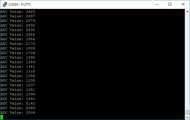
連続変換
プロジェクト:
https://github.com/ryood/STM32Cube_Test/tree/master/SW4STM32/Nucleo-F446_ADC_Polling_Continuous_Test1
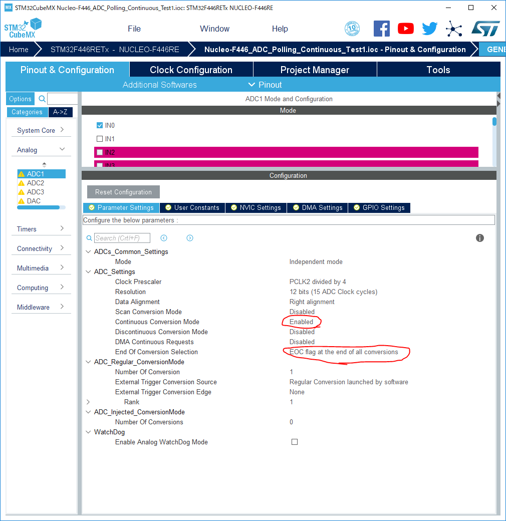
シングル変換と異なる点は、「ContinuousConvMode = ENABLE」とすることですが、Nucleo-F446REの場合は、EOCSelectionを「EOC flag at the end of all conversion」と指定する必要がありました。
参考「https://electronics.stackexchange.com/questions/202938/stm32-adc-conversion-using-hal」
調べるとUM1725の6.2.7の「HAL_ADC_PollForConversion」の項に以下の記述がありました。こんなのマニュアル読み込まないとわからない・・・。
This function cannot be used in a particular setup: ADC「EOC flag at the end of single channel conversion」のままだと、起動後1回だけADC変換が行われそれ以降は同じ値が返ってくるようです。
configured in DMA mode and polling for end of each
conversion (ADC init parameter "EOCSelection" set to
ADC_EOC_SINGLE_CONV). In this case, DMA resets the
flag EOC and polling cannot be performed on each
conversion. Nevertheless, polling can still be performed on
the complete sequence.
SW4STM32でコードを追加(一部抜粋)
  /* Initialize all configured peripherals */
  MX_GPIO_Init();
  MX_ADC1_Init();
  MX_USART2_UART_Init();
  /* USER CODE BEGIN 2 */
  /*##-3- Start the conversion process #######################################*/
  if (HAL_ADC_Start(&hadc1) != HAL_OK)
  {
    /* Start Conversation Error */
    Error_Handler();
  }
  /* USER CODE END 2 */

  /* Infinite loop */
  /* USER CODE BEGIN WHILE */
  while (1)
  {
    /* USER CODE END WHILE */

    /* USER CODE BEGIN 3 */
   /*##-4- Wait for the end of conversion #####################################*/
   /*  Before starting a new conversion, you need to check the current state of
        the peripheral; if it痴 busy you need to wait for the end of current
        conversion before starting a new one.
        For simplicity reasons, this example is just waiting till the end of the
        conversion, but application may perform other tasks while conversion
        operation is ongoing. */
   if (HAL_ADC_PollForConversion(&hadc1, 10) != HAL_OK)
   {
     /* End Of Conversion flag not set on time */
     Error_Handler();
   }

 /* Check if the continuous conversion of regular channel is finished */
   if ((HAL_ADC_GetState(&hadc1) & HAL_ADC_STATE_EOC_REG) == HAL_ADC_STATE_EOC_REG)
   {
     /*##-5- Get the converted value of regular channel  ########################*/
     uhADCxConvertedValue = HAL_ADC_GetValue(&hadc1);
   }
   printf("ADC Value: %d\r\n", uhADCxConvertedValue);
   HAL_Delay(100);
  }
  /* USER CODE END 3 */
連続変換モードにしてHAL_ADC_Start()をメインループの外に追い出せました。
メモ:
STM32CubeF4はSTM32CubeF3とはADCの仕様が結構異なり、「HAL_ADCEx_Calibration」がない模様。その他Dual channel(差動入力)がなかったり、Clock Prescalerで「ADC Asycrhronus clock mode」がなかったり・・・
参考になりそうな記事
「STM32F0 ADC - Tutorial 6」https://letanphuc.net/2016/07/stm32f0-adc/
「How to use 3 channels of the ADC in DMA mode using CUBE-MX and ATOLLIC」http://www.emcu.eu/how-to-use-3-channels-of-the-adc-in-dma-mode-using-cube-mx-and-atollic/
「How to use ADC in Interrupt mode」http://www.emcu.eu/how-to-use-adc-in-interrupt-mode/
「A detailed tutorial on STM32 ADC」https://visualgdb.com/tutorials/arm/stm32/adc/
0 件のコメント:
コメントを投稿